








Last Updated: 4 months ago
Every airline pilot and aviation enthusiast knows the Boeing 737 has muscle memory built into its DNA. It is a pilot’s airplane, retaining physical cable connections to the flight controls when modern competitors opted for fly-by-wire computers. Moving those control surfaces against hundreds of knots of slipstream requires immense power. That power comes from three robust hydraulic networks: System A, System B, and the unsung hero of worst-case scenarios—the 737 NG Standby Hydraulic system.
Pilots rarely think about the backup system during a routine line flight. It sits quietly in the background, waiting for a bad day to get worse. The real magic lies in how the Next Generation aircraft handles critical pressure losses without human intervention. The automatic activation logic is a masterclass in mechanical redundancy and electrical automation.
The Core Architecture of the 737 NG Standby Hydraulic Network
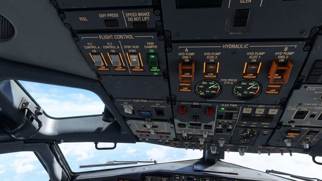
The 737 NG relies on System A and System B for normal operation. Each system uses an Engine-Driven Pump (EDP) and an Electric Motor-Driven Pump (EMDP). System A drops pressure at around 3,000 psi to move things like the ailerons, rudder, elevator, left thrust reverser, and flight spoilers. System B mirrors much of this power, handling the right thrust reverser, leading-edge flaps and slats, trailing-edge flaps, and autobrakes.
When both main systems lose pressure, or when specific aerodynamic configurations threaten aerodynamic control, the emergency network springs to life. Powered by a single 115V AC electric motor-driven pump, this isolated reservoir delivers 2,800 psi directly to the rudder, thrust reversers, and leading-edge flaps and slats (extend only).
| Feature | Main Systems (A & B) | 737 NG Standby Hydraulic System |
| Operating Pressure | 3,000 psi (207 bar) | 2,800 psi (193 bar) |
| Power Sources | 1 EDP & 1 EMDP per system | 1 dedicated 115V AC EMDP |
| Fluid Capacity | ~5.7 gal (A) / ~8.2 gal (B) | ~3.6 gallons (Standby Reservoir) |
| Primary Targets | Full flight controls, landing gear, flaps | Rudder, Thrust Reversers, LE Flaps/Slats |
| Activation | Continuous manual/engine operation | Automatic logic or manual FLT CONTROL switch |
Inside the 737 NG Standby Hydraulic Auto Activation Matrix
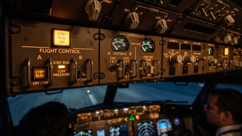
Pilots can manually select the backup system using the Flight Control switches on the overhead panel, shifting them from “ON” to “STBY RUD”. The real engineering brilliance is the automatic activation circuit. Boeing designed a system that monitors fluid pressure, flight control switch positions, wheel speed, and airborne status to protect the aircraft when the crew is buried in checklists.
The automated pump kicks in when specific conditions align in the background. The system looks for a drop in pressure below a critical threshold—typically around 1,300 psi—in either System A or System B.
The Flaps Extended Scenario
The most common automatic activation pathway occurs during takeoff or landing approach. The aircraft configuration must meet these parameters:
- The aircraft is airborne or running down the runway with a wheel speed greater than 60 knots.
- Either Flaps Switch is not UP (meaning trailing edge or leading edge flaps are deployed).
- Main System A or System B pressure falls below 1,300 psi.
- The respective Flight Control switch remains in the normal “ON” position.
This logic ensures that during high-workload phases of flight near the ground, a sudden loss of an engine pump or a major line rupture will not cause uncommanded roll or pitch variations before the pilots can react.
The Force Trim Shield
The automated logic acts as a shield against aerodynamic stalls or severe control anomalies through the Force Trim System. The pump starts automatically if:
- Main System A or System B pressure drops below 1,300 psi.
- The aircraft is airborne.
- The Flaps Switch is UP.
- An aerodynamic condition triggers the Flaps Drive or Force Trim system to demand emergency stabilization.
Hardware Components of the 737 NG Standby Hydraulic Assembly
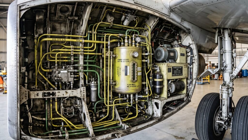
The brain of this operation relies on physical pressure sensors and control valves located in the wheel well and hydraulic service bays.
- The Standby Reservoir: Located in the trailing edge of the left wing root/wheel well area. It receives its fluid directly through a small balance line from the System B reservoir. If System B leaks entirely dry, a standpipe design leaves enough fluid in the bottom of the B reservoir to keep the standby network topped off.
- Pressure Switches: Calibrated to detect the exact drop to 1,300 psi. They send a 28V DC signal to the pump control relays.
- The Standby Rudder Shutoff Valve: A motor-operated valve that opens when auto-activation occurs, sending the 2,800 psi flow straight to the standby actuator on the main rudder PCU (Power Control Unit).
Legacy Classic vs. Next Gen System Evolutions
Aviators transitioning from the older 737 Classic (-300/-400/-500) to the NG (-700/-800/-900) often notice how much smarter the newer airframe is. On the 737 Classic, the standby system was more rudimentary. The automatic activation was tied tightly to a complete loss of System A or B without the nuanced airspeed and flap position filtering found on the NG.
Boeing redesigned the logic for the NG to prevent unnecessary pump cycling. The 115V AC electric pump draws massive current from the AC Transfer Busses. Starting that pump under low-load conditions creates unnecessary thermal stress. The NG logic ensures the pump runs only when the aerodynamic demands of the flight path dictate emergency pressure.
What the Pilot Sees in the Flight Deck
When the auto-activation logic triggers, the cockpit remains surprisingly quiet. There is no loud master caution chime solely for the pump starting. The crew will notice the yellow STBY RUD ON light illuminate on the overhead flight control panel. This tells the pilots that the standby pump is running and the standby rudder shutoff valve has opened.
At the same moment, the master caution light will capture their attention, accompanied by the LOW PRESSURE lights for the failed main system (A or B). The flight controls will feel slightly different through the yoke and rudder pedals, but control authority remains intact. The backup system seamlessly keeps the aircraft tracking down the localizer or executing a safe go-around.
Frequently Asked Questions
Can the 737 NG Standby Hydraulic system retract the landing gear?
No. The standby system is a get-home-safe system designed for control, not convenience. It lacks the volume and pressure to actuate heavy loads like the landing gear or trailing edge flaps. It can only extend the leading edge flaps and slats using a dedicated standby power unit.
How does the backup system get its fluid if System B suffers a total leak?
The System B reservoir utilizes a standpipe for its fluid supply to the main pumps. If a leak occurs in the main lines of System B, the fluid level drops until it reaches the top of the standpipe. The fluid below that level cannot escape through the leak and remains reserved exclusively to feed the standby reservoir.
What happens if the aircraft loses all electrical power during auto activation?
The standby hydraulic pump requires 115V AC power, normally supplied by AC Transfer Bus 1 or 2. If the aircraft loses all main AC generators, the standby pump can be powered by the APU generator. If total AC power fails down to the batteries, the standby pump will stop, and the aircraft will rely on manual reversion.
Join the Conversation
The balance between mechanical simplicity and smart automation is what makes the 737 NG such an enduring piece of engineering. Have you ever experienced a hydraulic system failure in the simulator or real life? How do you feel about Boeing keeping physical cable backups versus the pure fly-by-wire architecture of modern airliners? Let us know your thoughts in the comments below!
Did you know AviationStream.com has a YouTube channel? Check out TheAeroGraphyOfficial and subscribe to watch fun, highly engaging aviation Shorts!