







Last Updated: 4 months ago
When analyzing modern aerospace engineering, the debate surrounding fly by wire vs fly by light control systems represents a massive technological shift. Flight control systems progress through continuous optimization of weight, reliability, and signal transmission speed. For decades, mechanical linkages dictated aircraft design. Heavy setups used steel push-pull rods, cables, pulleys, and bellcranks. Because of this layout, legacy configurations required massive structural volume. They added dead weight and demanded intensive maintenance to counteract continuous cable stretch.
Commercial and military aircraft grew larger and faster over time. Soon, aerodynamic forces exceeded human physical strength. This operational shift forced engineers to integrate hydraulic boost loops. The real transformation occurred when designers decoupled pilot movements from control surfaces entirely. Aerospace teams transitioned away from heavy cables and pulleys by implementing the exact fly by wire flight control technology standards to optimize aerodynamic efficiency. This step replaced mechanical pathways with analog and digital electronic networks. Today, the industry faces another major structural shift. We are moving from electron transport over copper pathways to photon transmission through fiber-optic networks.
Defining the Architecture: What is Fly-by-Wire?
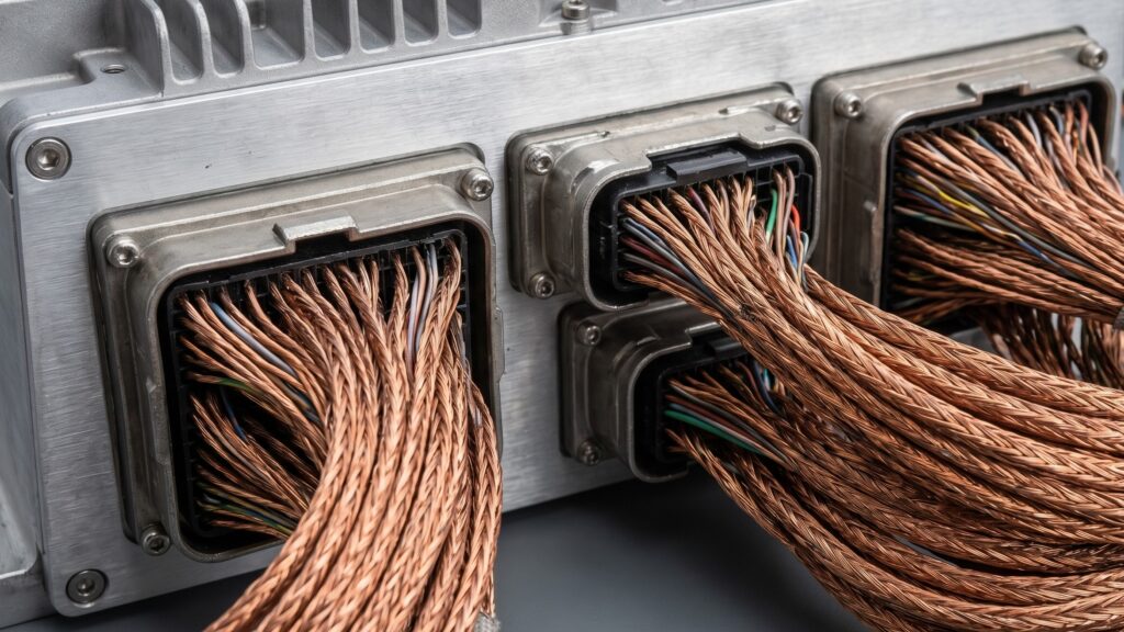
To understand digital FBW networks, you must trace the signal path from the cockpit to the control surface. The process starts at the pilot interface. When a pilot moves a sidestick, special transformers detect the physical displacement. These LVDT or RVDT sensors convert physical position into analog AC voltage signals. Then, these signals travel via shielded copper wiring harnesses directly to the central processing hardware. Modern aviation relies heavily on this fly by wire flight control technology to maintain stable flight characteristics. Following this step, analog-to-digital converters transform the voltage spikes into binary data streams.
The core processor assesses these inputs against real-time parameters. This dataset includes angle of attack, static pressure, dynamic pressure, and angular acceleration rates. Engineers tracking this operational genealogy will find the Airbus A320 flight computers explained guide valuable. It shows how decentralized computing architectures track pilot inputs. In addition, the computers send calculated outputs to command the servo valves on the main actuators. This transport layer relies heavily on ARINC 429 protocols. This protocol operates as a one-way serial bus up to 100 kbps. Modern designs use ARINC 664 (AFDX), which leverages deterministic Ethernet networks running at 100 Mbps.
The Optical Evolution: What is Fly-by-Light?
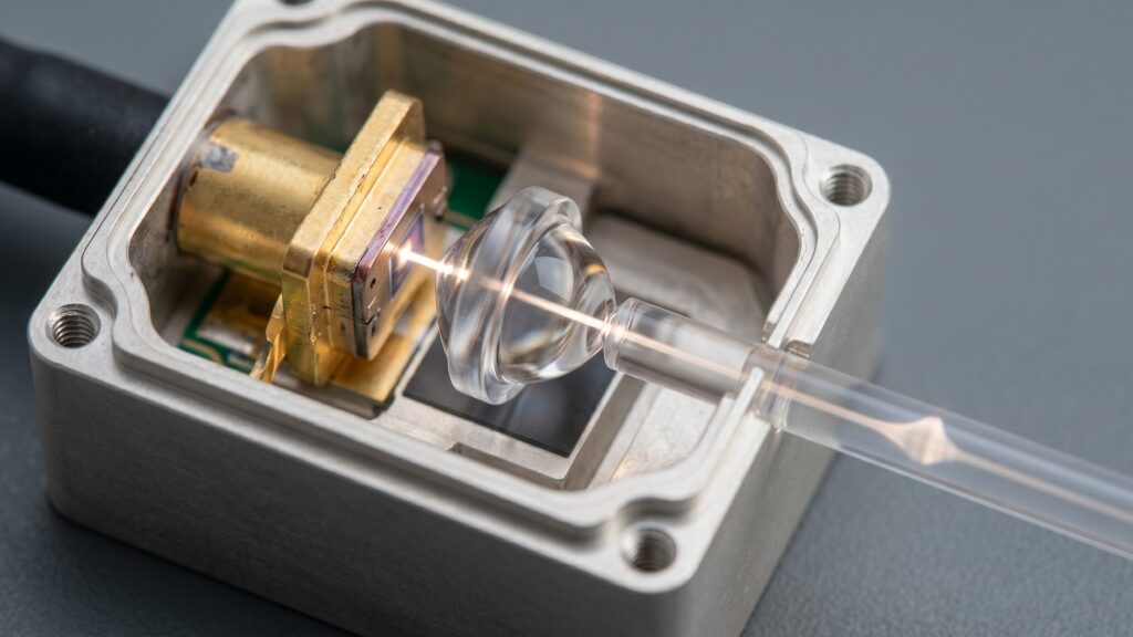
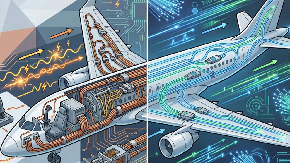
Implementing a fly by light architecture retains the core computing logic of advanced digital flight systems. Instead of copper wires, it introduces specialized fiber-optic cabling networks. This underlying transformation changes how data moves across the airframe. Deploying a fly by light architecture modulates light waves through high-purity silica glass or plastic optical fiber cores. In contrast, traditional control networks rely on modulated electrical currents running through copper.
An FBL control loop starts similarly to a standard digital loop. It captures pilot inputs but completely changes the output phase of the computing system. The electrical digital command signals pass through an optical transceiver module. This component uses a semiconductor laser diode to convert electrical bits into high-frequency pulses of light. These systems operate at near-infrared wavelengths like 850 or 1310 nanometers. Photons travel through the fiber-optic cable utilizing the physics of total internal reflection. The cable features a high-purity glass core surrounded by a lower-index cladding layer. At the actuator interface, a photodiode captures the incoming light pulses. The sensor converts the optical energy back into an electrical signal to drive local hydraulic components.
Technical Deep Dive: Fly by Wire vs Fly by Light
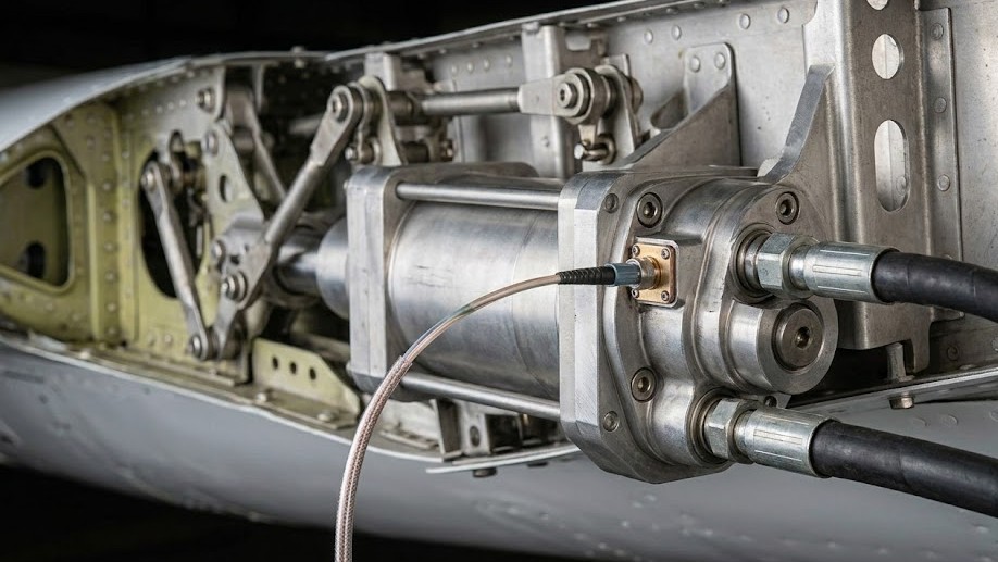
Evaluating the performance vectors of fly by wire vs fly by light protocols requires looking closely at processing hardware, line structures, and safety layouts. Both systems run complex control commands, but their physical components experience different environmental stresses.
flight control computer integration
The Flight Control Computer (FCC) acts as the brain of the entire aircraft. When reviewing flight control computer integration parameters, processing units must handle complex calculations while managing copper vulnerabilities. The engineering behind flight control computer integration changes slightly in an FBL architecture. The core processor logic remains identical. Instead of copper interfaces, the input/output modules handle optical transceivers directly. This design eliminates heavy internal metal shielding within the computer chassis. Optical inputs remain completely immune to cross-talk, induction, and voltage spikes.
Redundancy Frameworks
Safety mandates require extreme architecture configurations to prevent catastrophic structural losses. Aerospace installations implement Redundancy (Triple/Quadruple Redundancy) configurations across their computing nodes. A typical quadruple redundant system uses four independent channels. Each channel has its own wiring harness. Operators route these lines along different structural ribs of the airframe. This layout prevents a single engine failure or shrapnel impact from disabling the entire flight network.
These computing channels employ cross-channel data links to vote on the correct command output. If one computer provides an anomalous value, the remaining three channels override it. In an FBL layout, this cross-talk occurs over fiber-optic lines. This strategy removes the risk of lightning surges propagating across channels.
Hydraulic and Electrical Actuators
The final stage of flight control is physical actuation. Modern designs utilize Hydraulic and Electrical Actuators. These include electro-hydraulic actuators (EHAs) or electrical backup hydraulic actuators (EBHAs). In an FBW system, these units receive electrical currents to position a torque motor. The motor then modulates hydraulic fluid flow into the piston chambers. FBL systems require opto-hydraulic actuators or local smart actuation microprocessors. An opto-hydraulic actuator uses the received optical power directly. Alternatively, it relies on a local electrical power rail to decode the optical message. This approach completely isolates high-power actuation circuits from low-power optical signaling lines.
Control Laws and Flight Envelope Protection
The divergence between pilot authority and automated intervention is clear in modern jets. You can study the Boeing 777 vs Airbus A350 fly by wire logic comparison to see this philosophical divide. Both FBW and FBL architectures depend on real-time execution of complex flight control laws. These safety guardrails rely on continuous calculations of aerodynamic limits. The software integrates flight envelope protection and PID control in avionics to modulate control surface deflections safely. This process avoids exceeding structural yield points.
The software utilizes Proportional-Integral-Derivative (PID) feedback loops. These algorithms damp out atmospheric disturbances and uncommanded oscillations. FBL networks offer significantly higher data bandwidth. Because of this, they execute feedback calculations at higher sampling frequencies. This capability results in tighter control surface tracking. It also creates smoother transitions during high-turbulence encounters. The implementation of Flight Envelope Protection remains absolute, keeping the aircraft within safe parameters.
Electromagnetic Interference Challenges
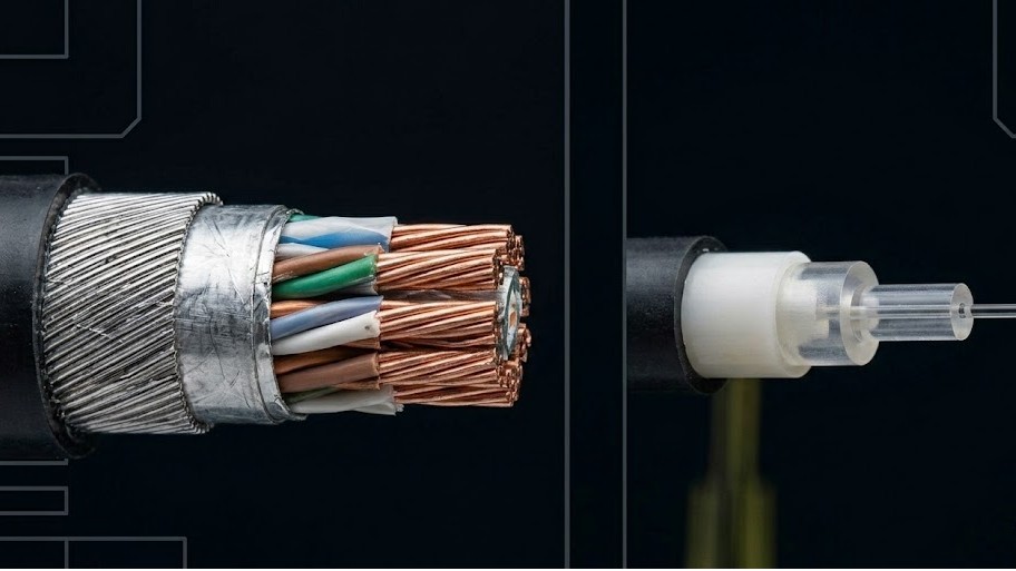
The core differentiator centers around electromagnetic vulnerability. Managing electromagnetic interference challenges is a primary concern for traditional copper designs. Copper wiring acts as a long antenna distributed throughout an airframe. When an aircraft encounters High-Intensity Radiated Fields (HIRF), large voltages can develop along these copper lines. Modern engineering teams solve these electromagnetic interference challenges by completely isolating the transmission medium.
To protect sensitive FCC inputs, FBW cables require heavy shielding. This shielding consists of metal braiding, conductive conduits, and surge suppressors. In contrast, fiber-optic cables are made of non-conductive dielectric materials. Photons moving through glass remain entirely unaffected by external fields. This trait removes the need for heavy EMI shielding.
Signal Attenuation Challenges
While a fly by light architecture solves the EMI problem, it introduces signal attenuation challenges. As light travels through an optical fiber, it loses power. Absorption, scattering, and structural bending cause this degradation. Managing optical connector losses remains a major engineering challenge. A copper pin contact can tolerate minor dust and moisture. Instead, a single speck of dust on a fiber-optic ferrule can block light pulses completely. This contamination causes total signal loss. Furthermore, tight bends in the fiber routing can exceed the critical angle of reflection. This mistake leaks light into the cladding and reduces signal integrity at the receiver.
Comparative Evaluation Matrix
| Parameter | Fly-by-Wire (FBW) | Fly-by-Light (FBL) |
| Transmission Medium | Shielded copper twisted-pair / coaxial cabling | Silica glass or plastic optical fiber (POF) |
| EMI Susceptibility | High; requires heavy shielding and surge protection | Complete immunity to HIRF, lightning, and EMP |
| Weight / Fuel Efficiency | Heavy due to copper density and shielding layers | Exceptionally lightweight; reduces fuel burn |
| Data Bandwidth | Limited (Up to 100 Mbps in advanced AFDX networks) | High (Multi-gigabit capacity per channel) |
| Failure Modes | Short circuits, open circuits, corrosion, cross-talk | Micro-bending loss, connector contamination, brittle fracturing |
| Maintenance Profile | Standard pin testing, simple splicing protocols | Requires specialized optical time-domain reflectometers (OTDR) |
Real-World Applications and Experimental Paradigms
From an operational standpoint, maintaining avionics hardware presents completely distinct challenges for line mechanics. The implementation of FBL has moved from academic research to operational platforms. Early flight validations occurred on test aircraft like the NASA F/A-18 Systems Research Aircraft. This program evaluated optical sensor suites and flight control links under high-g conditions.
The most notable production application exists on the Kawasaki P-1 maritime patrol aircraft. The P-1 utilizes an FBL flight control system to eliminate radar interference risks. By replacing the copper infrastructure with fiber optics, Japanese engineers reduced airframe weight. This move also prevented powerful surface search radars from disrupting flight control loops. Military configurations favor FBL for its resistance to combat damage. An optical fiber bundle does not pose a short-circuit risk if severed by ballistic fragments.
Deep-Tech Frequently Asked Questions
How does an FBL system maintain functionality during a total electrical failure?
An FBL system still requires electrical power to run its flight computers and transceivers. Light cannot perform logical operations or drive heavy actuator surfaces alone. In a total electrical emergency, primary generators fail. The system then relies on an Emergency Power Unit (EPU) or a Ram Air Turbine (RAT). The RAT deploys into the airstream to generate localized electrical power. This power passes through Transformer Rectifier Units to create clean 28V DC power. This line feeds the FCCs and optical transceivers exclusively. The optical communication lines remain functional as long as this local rail powers the transceivers.
Do high-g maneuvers cause signal degradation in fiber-optic systems due to micro-bending?
High-g maneuvers flex the aircraft structure, introducing deflection along the wings and fuselage. This mechanical stress can cause micro-bending in fiber-optic cables if installed poorly. Micro-bends create microscopic imperfections along the core-cladding boundary. This problem causes light rays to scatter and escape the core, which increases signal attenuation. To prevent this issue, aerospace-grade optical fiber features specialized mechanical buffer coatings. Engineers route these lines within protective flexible conduits. The cabling layout includes deliberate service loops at structural joints. This feature ensures airframe flexing does not subject glass cores to damaging strains.
Can a broken fiber-optic cable be repaired in the field during line operations?
Repairing a broken fiber-optic cable is more demanding than splicing a copper wire. Technicians cannot simply crimp conductors together in the hangar. A damaged aerospace optical fiber requires a fusion splice or a precision mechanical splice. A fusion splice requires a specialized field-deployable arc-fusion machine. This device aligns the glass cores down to a tolerance of less than 1 micron. Then, it melts them together using a localized electric arc. The technician must perform this repair in a clean environment. They cleave the fiber faces cleanly and inspect them with a microscope to ensure no dust particles trap light.
As aviation moves forward, the choice between fly by wire vs fly by light configurations will shape the next generation of clean-sheet aircraft designs. Will commercial transport aircraft stick with refined, deterministic Fly-by-Wire setups, or will the weight savings and EMI immunity of Fly-by-Light prompt a fleet-wide shift? Let us know your thoughts on fiber routing, opto-hydraulics, and maintenance protocols in the comments below.
Did you know AviationStream.com has a YouTube channel? Check out TheAeroGraphyOfficial and subscribe to watch fun, highly engaging aviation Shorts!